Sunday, 8 May 2011
Friday, 6 May 2011
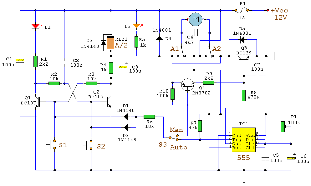
Automatic Curtain Control
Using switch S3 also allows manual control, allowing for curtains to be left only partially open or closed. The circuit controls a motor which is attached to a simple pulley mechanism, to move the curtains. I first started this circuit over 20 years ago and apart from now using metal gears, very little has changed.

Notes:
Automatic Operation
The circuit can be broken down into three main parts; a bistable latch, a timer and a reversing circuit. Toggle switch S3 determines manual or automatic mode. The circuit as shown above is drawn in the automatic position and operation is as follows. The bistable is built around Q1 and Q2 and associated circuitry and controls relay A/2. S1 is used to open the curtains and S2 to close the curtains. At power on, a brief positive pulse is applied to the base of Q2 via C2. Q2 will be on, and activate relay A/2.
The network of C3 and R4 form a low current holding circuit for the relay. Relay A/2 is a 12V relay with a 500 ohm coil. It requires slightly less current to keep a relay energized than it does to operate it. Once the relay has operated, the current through the coil is reduced by R4, saving power consumption. When Q2 is off, C3 will be discharged, but when Q2 becomes active (either at switch on or by pressing S1) capacitor C3 will charge very quickly via the relay coil. The initial charging current is sufficient to energize the relay and current flow through R4 sufficient to keep it energized.
Q1 bias is applied via R3 which is tied to Q2 collector. As Q2 is on, the collector voltage will be low, close to 0v and therefore Q1 and LED L1 will be off. As Q1 is off, its collector voltage will be high, and Q2 bias voltage is applied via the chain L1, R1 and R2. The curtains should already be fully open.
If now S2 is pressed, the base voltage of Q2 will become 0 and Q2 will switch off. In switching off, its collector voltage will rise to the supply voltage and Q1 will now be forward biased via the relay coil A/2, R4 and R3. LED L1 will now be lit, relay A/2 will be de-energized and as Q1 collector will be low, Q2 will be off and the circuit latched in this condition.
At the same time as S2 is pressed, the trigger input of IC1, a 555 timer (normally held high via R7 will be taken low. A timing sequence now commences. Duration is controlled by preset P1 and C6 and the timing is adjustable between about 1 and 12 seconds. This delay is adjusted so that the motor will run for sufficient time to fully open or close the curtains. The output of the 555 turns on Q3, fed via R8 which now applies power to the motor via relay contacts A1 and A2.
At any time the motor is in operation, and for any direction, LED L2 will always be lit. Contacts A1 and A2 reverse the polarity of the voltage appearing at the motor terminals,
Wednesday, 4 May 2011
12v DC to 24v DC converter
This simple DC-DC converter can provide up to 24V from a 12V source. It can be used to run radios, small lights, relays, horns and other 24V accessories from a 12V vehicle with a maximum draw of about 800mA. It can be used to charge one 12V battery from another, or step up the voltage just enough to provide necessary overhead for a 12V linear regulator. Using one op-amp as a squarewave oscillator to ring an inductor and another op-amp in a feedback loop, it won't drift around under varying loads, providing a stable 24V source for many applications. With a wide adjustment in output this circuit has many uses

:Here is circuit diagram:


Rain Alarm Circuit . . . .
Rain alarm circuit is very useful if the rainy season, the function of a series of rain this alarm is to remind us in case of rain. In the circuit diagram is controlled by the IC 555, which functions for the NE555 provides 1 Khz tone through the speaker if the sensor exposed to rain. Water sensor images can be seen in the picture, place the sensor at an angle of 30-45 degrees from the ground. Global Water’s Water Level Alarm Sensor (WA600) is water solid state sensors for detecting the presence of conductive solutions, such as water spills, water tank levels, and drainage ponds. Water alarm sensor has two stainless steel electrodes in the position at the desired point for the detection of liquid. When liquid is detected, a relay close to the surface water and the alarm signal can be used to sound an alarm or closing a switch inside a piece of remote monitoring equipment. Relay outputs fully isolated and can handle 2 amps of current. The following is a schematic drawing:

After the alarm sensor water level in dry conditions, the detection sensor will automatically reset without the need for additional services. Alarm surface rough and require minimal maintenance. The Water Level Alarm has many uses, including: surface water monitoring, detection precision, control water levels, an indication of high water, and sea submarine low-level indication. Water alarm circuits can be purchased to trigger an alarm on contact with water or air
Monday, 2 May 2011
Water Level Indicator
Water Level Indicator
Description
This is the circuit diagram of a simple corrosion free water level indicator for home and industries.In fact the the level of any conductive non corrosive liquids can be measured using this circuit.The circuit is based on 5 transistor switches.Each transistor is switched on to drive the corresponding LED , when its base is supplied with current through the water through the electrode probes.
One electrode probe is (F) with 6V AC is placed at the bottom of tank.Next probes are placed step by step above the bottom probe. When water is rising the the base of each transistor gets electrical connection to 6V AC through water and the corresponding probe.Which in turn makes the transistors conduct to glow LED and indicate the level of water.The ends of probes are connected to corresponding points in the circuit as shown in circuit diagram.Insulated Aluminum wires with end insulation removed will do for the probe.Arrange the probes in order on a PVC pipe according to the depth and immerse it in the tank.AC voltage is use to prevent electrolysis at the probes.So this setup will last really long.I guarantee at least a 2 years of maintenance free operation.That’s what I got and is still going.
Components
T1 – T5 BC 548 or 2N2222 Transistors
R1-R5 2.2K 1/4 W Resistors
R6-R10 22K 1/4 W Resistors
D1 – D5 LED’s ( color your choice)
Notes:
Use a transformer with 6V 500 mA output for power supply.Do not use a rectifier! we need pure AC. Use good quality insulated Aluminum wire for probes.If Aluminum wires are not available try Steel or Tin.Copper is the worst.Try the circuit first on a bread board and if not working properly, make adjustments with the resistance values .This is often needed because conductivity of water changes slightly from place to place.The type number of the transistors used here are not critical and any small signal NPN transistor will do the job. Few other suitable type numbers are BC546, BC107, PN2222, BC337, BF494, ZTX300, BEL187 etc. The circuit can be enclosed in a plastic box with holes for revealing the LEDs .
Water Level Indicator Circuit Diagram and Sensor Arrangement.

Simple Fire Alarm circuit
Here is a simple fire alarm circuit based on a LDR and lamp pair for sensing the fire.The alarm works by sensing the smoke produced during fire.The circuit produces an audible alarm when the fire breaks out with smoke.
When there is no smoke the light from the bulb will be directly falling on the LDR.The LDR resistance will be low and so the voltage across it (below .6V).The transistor will be OFF and nothing happens.When there is sufficient smoke to mask the light from falling on LDR, the LDR resistance increases and so do the voltage across it.Now the transistor will switch to ON.This gives power to the IC1 and it outputs 5V.This powers the tone generator IC UM66 (IC2) to play a music.This music will be amplified by IC3 (TDA 2002) to drive the speaker.Resistor R6 is meant for protecting the transistor when R4 is turned towards low resistance values .Resistor R2 and R1 forms a feedback network for the TDA2002 and C1 couples the feed back signal from the junction of R1 & R2 to the inverting input of the same IC.
The diode D1 and D2 in combination drops 1.4 V to give the rated voltage (3.5V ) to UM66 .UM 66 cannot withstand more than 4V.
Circuit diagram with Parts list.

Fire alarm circuit
- The speaker can be a 32Ω tweeter.
- POT R4 can be used to adjust the sensitivity of the alarm.
- POT R3 can be used for varying the volume of the alarm.
- Any general purpose NPN transistor(like BC548,BC148,2N222) can be used for Q1.
- The circuit can be powered from a 9V battery or a 9V DC power supply.
- Instead of bulb you can use a bright LED with a 1K resistor series to it.
Subscribe to:
Posts (Atom)